Ethernet, CSMA/CD and MAC Address
Hello everyone with a new blog post! I am here with the 4th blog post of the network basics series. Have a good read in advance.
Summary
In this blog post, we will continue with the TCP, UDP Protocols and TCP/IP Model that we have already covered, and we will move on to the basic concept of Ethernet. Let’s make a quick start to this article, starting with the history of Ethernet and extending to the MAC address.
Ethernet and the History of Ethernet
Ethernet is a protocol that emerged in the 1970s. It can operate in layers 1 and 2 in the OSI model. This protocol includes features such as signaling in the first layer and defining frame formats in the second layer.
Ethernet was developed by a company called Xerox Parc between 1973 and 1975. In 1975, when the protocol was completed, a patent application was filed. In 1976, the first draft text for this protocol was prepared. The first draft model included a data rate of 3Mbps and 8 Bit source and destination address fields.
Robert Metcalfe, one of the developers of the protocol, founded 3COM in 1979. Through Robert, who convinced DEC, Intel and Xerox to develop Ethernet as the “DIX” standard, the first Ethernet draft was published by the IEEE in 1980. After a 3-year hiatus, it was adopted by the IEEE in 1983 as the IEEE 802.3 standard.
When these standards were adopted by the IEEE, the Ethernet protocol had a data rate of 10Mbps and a 48 Bit data source and destination address space. The 48 Bit data source and destination address space is the MAC address used today.
Ethernet and Topologies
Ethernet had a topology like every network. As seen in the first ethernet drafts and as I mentioned in my previous blog post on network topologies, Ethernet used the topology model called “Bus Topology” in the first titles. When a data was sent, all devices connected to the line on the network could receive this data. Old wired telephone lines can be given as an example.
When we continue with the first topology designed on Ethernet, we cannot pass without mentioning the cable technology of this topology. The first Ethernet-based cable standards on this topology were 10Base5 and 10Base2.
In these cables, 10Base5 can be used up to a maximum of 500 meters. However, 10Base2 can be used up to a maximum of 185 meters.
Well, when we examine these cable standards here, we come across a format on the nomenclature. These are naming formats as 10-Base and 5 or 2. Here the 10 part tells us that the cable supports a maximum data rate of 10Mbps, the Base word is “Baseband” and 5 or 2 tells us that 10Base5 has a segment width of 500 meters and 2 in 10Base2 has a maximum segment width of 185 meters.
Also good information:
Baseband, when only one signal is transmitted on a cable at the same time, the word Base is used in the nomenclature to be Baseband. It means that a single signal or frequency is transmitted on a single cable. If a second signal is sent on the cable contrary to the Bus topology, then the collision process we call Collision occurs. To avoid these collisions, cables with Broadband technology should be used, not Baseband. An example of this is the cables used to display images to televisions at home. Cables used for TVs can carry different signals on a single cable. The best example of this is that the signals of different channels come on the television at the same time and we can get it over a single cable.
Continuing from where we left off, in this topology model, a connector called BNC-T is used to connect the computers to each other. Topology is provided through this Connector. After all computers are connected and the networking process is completed, the process is terminated by attaching the terminators called BNC Terminators to the cable end. If this termination process is not done at the end of the cabling, the data transmitted on the cable is reflected back and collision occurs. Well, since we are talking about the issue we call collision, we cannot do without mentioning CSMA/CD, which is a solution to this. So CSMA/CD is next.
What is CSMA/CD?
In the early days of Ethernet, the devices on the bus topology and connected to the topology provided data transmission via CSMA/CD. CSMA/CD also stands for Collision Detection Carrier Listening Multiple Access. However, in a nutshell, its main task is to detect whether there is Collision or not, hence the name Collision Detector.
In this method, when a device wants to send data over the topology, it is detected whether there is active data transport in the topology via CSMA/CD. The tasks here are CS to determine whether the communication line is suitable for sending data, MA to prevent other devices on the topology from sending data except the device sending and receiving the data, and even to ensure that only the devices sending and receiving data remain in communication, and CD to detect the collision of data sent by devices sending data at the same time when the line of devices connected to the topology is long. This is how CSMA/CD comes into existence.
CSMA/CD sends a JAM signal in order to provide MA (Multiple Access) on the topology and the communication of other devices on the network is stopped except for the device sending and receiving data.
A little information:
The more devices connected to each other on the topology, the higher the probability of Collision. This is not only due to the connected device, but also due to the length of the cable and if there is a fault in the cable. As we remember, in case of a cable failure, the signal is not attenuated by the signal attenuator, so the signal is reflected back and Collision occurs again.
So we talked about this Bus topology and Collision. If it is such a problematic topology, why didn’t we switch to another topology, right? Yes, we did. Yes. As a solution to such problems, Star Topology was adopted, taking into account the disadvantages of 10Base2 and 10Base5. As it is less costly and more advantageous compared to Bus, Bus was abandoned and Star topology was started to be used.
OK, we have seen Collision in the disadvantages of Bus, we have seen Collision in Cables, but there are also areas. You can think of these areas as domains. The domain of Collision. Let’s continue without much ado. What is Collision Domain?
What is Collision Domain?
In the early days of Ethernet, we often saw that there could be data collision between devices created with Bus Topology. However, there are domains as a result of signal collision. Now let’s continue in order.
Single Collision Domain:
In case of a collision in the topology, if all devices in the topology are affected, then the domain of the collision is called Single Collision Domain. In bus topology, since all devices are connected to a single cable and if a signal collision occurs in this topology, we call it a single collision.
Broadcast Domain:
In this area, if the broadcast sent in the topology is received by all devices, we call this topology a broadcast domain. There may be a concept confusion here. Broadcast Domain is also Single Collision Domain. However, Broadcast Domain is also Single Collision Domain. It is complicated but understandable. I will talk about this in more detail later. Now let’s continue over Ethernet and move on to Ethernet Cable Types.
Ethernet Cable Types
We examined the 10Base2 and 10Base5 cable types used on the Bus topology created in the early days of Ethernet. Then, when we progressed through the Star topology, we met Twisted Pair Cables. When we progressed through the Star Topology, standards were created in this topology, just like the Bus. 10BaseT used in this topology was standardized in 1990. In these standards, the maximum cable length is limited to 100 meters. It is Baseband and supports up to 10Mbps data rate. In addition, as in the same Bus standards, the expression T, which replaces the expression 2 or 5, indicates that we have Twisted Pair.
Here 10BaseT is divided into two. These are UTP and STP. If I summarize it simply; UTP: means Unshielded Twisted Cable, STP means Shielded Twisted Cable. which, technically speaking, consists of 4 pairs of 2 cables. Twisted is one of the most basic elements to prevent frequency collision. RJ45 connector is used as a connector. RJ45 also has 2 different pin placement types in the same way. You can examine in detail from the picture below.
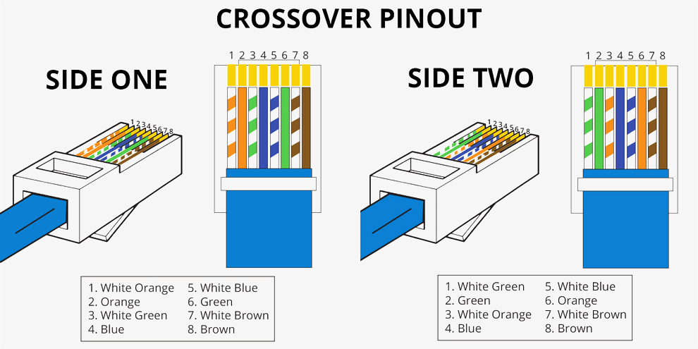
However, these were not very up-to-date today. Since automatic MDI and MDIX have been introduced, data flow and connection can be provided on the same connector whether it is T568A or T568B. Now let’s continue with the last part of our Network 101 series, MAC Address.
MAC Address
When defining Ethernet, I have already mentioned that Ethernet works on both layer 1 and layer 2. When Ethernet standards are accepted, not only layer 1 but also layer 2 is accepted. Ethernet has a MAC address in the data link layer.
What is MAC Address?
MAC, or Media Access Control Address, can also be referred to as physical address or hardware address. MAC Address is not only available on Ethernet. MAC Addresses:
- Ethernet,
- Token Ring,
- Wi-Fi,
- Bluetooth
It is also used in protocols such as
MAC Address is a value consisting of 48 bits and 6 bytes and is uniq for each network card. This value is given to the network cards by the hardware manufacturer. MAC Address consists of 6 bytes. The first 3 bytes represent the manufacturer and the other 3 bytes are the unique code given to the hardware produced by the company.
What is the Role of the MAC Address?
MAC Address enables network devices to communicate in local networks. It is not a value carried outside the network. When a device wants to establish a connection with another device in the network, it does this through the MAC Address. Briefly, this addressing method is used to identify and communicate with the device that will send the data and the device that will receive the data when two devices communicate with each other within the same network.
If you are here, it means that you now have a basic level of Network knowledge. The important thing here is not that you have come this far, but that you are evaluating all this information I have written in a way that will benefit you. As much as I could, I tried to convey the Network 101 series to you in a fluent, understandable and plotted way. Hope to see you with the Network 102 series.
